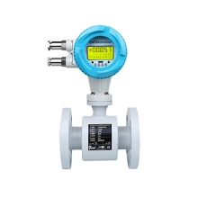
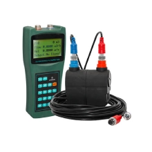
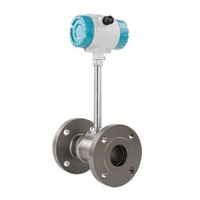
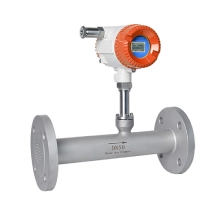
Introductions
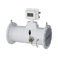
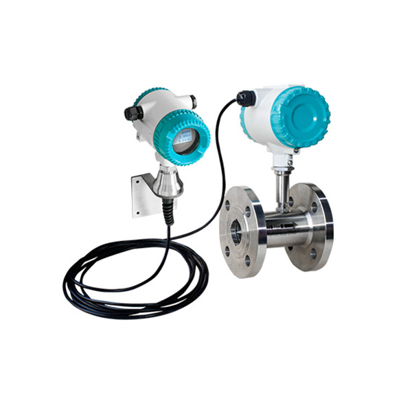
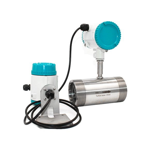
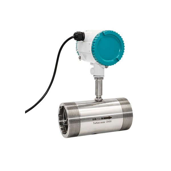
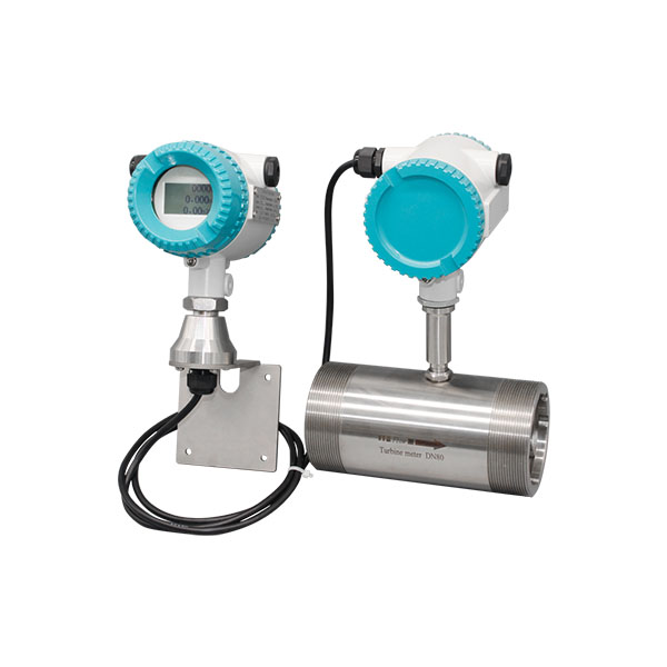
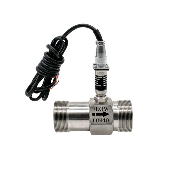
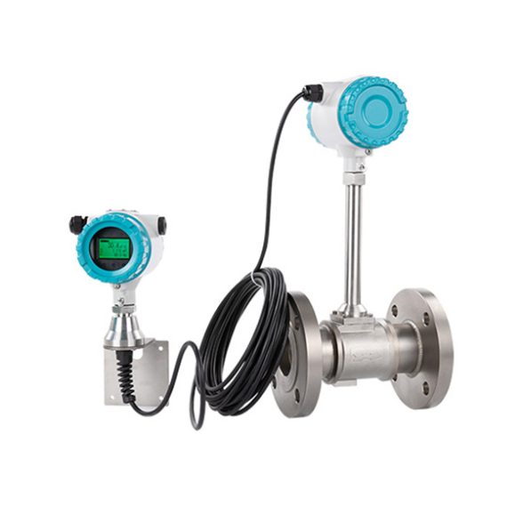
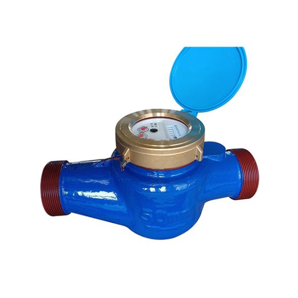
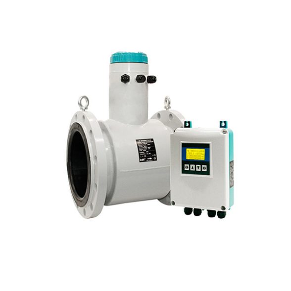
WESDUN is a manufacturer specializing in the production of Turbine flow meter;Battery-powered flow meter.Turbine flow meter consists of turbine flow sensor and display instrument and it is made by us using foreign state-of-the-art technologies, which is an ideal gauge for measuring of liquid flow.
This flow meter is characterized by simple structure, high precision and easy installation and repair.
It may be used in a wide range of industries, including oil industry, chemical industry, metallurgy, water supply, paper-making, environment protection and food industry.
Main technical Parameters
| Size & Process Connection | Thread connection: DN4,6,10,15,20,32,40,50,65,80,100 Flange connection: DN15,20,32,40,50,65,80,100,125,200 Clamp connection: DN4,6,10,15,20,32,40,50,65,80,100 | |
| Accuracy | ±0.5%, ±0.2% Optional | |
| Sensor Material | SS304,SS316L Optional | |
| Ambient Conditions | Medium temperature: | -20C~+150C |
| Atmospheric pressure: | 86Kpa~106Kpa | |
| Ambient temperature: | -20°C~+60C | |
| Relative humidity: | 5%~90% | |
| Signal Output | Pulse, 4-20mA,Alarm(optional) | |
| Digital Communication | RS485, MODBUS; HART | |
| Power Supply | 24V DC/3.6V Lithium Battery | |
| Cable Entry | M20*1.5;1/2″NPT | |
| Explosion-proof class | Ex d IIC T6 Gb | |
| Protection class | IP65; IP67 Optional | |
| Diameter(mm) | Standard Range(m3/h) | Extended Range(m3/h) | Connection Standard(Optional) | Standard Pressure(Mpa) | Customized Pressure Rating(Mpa) |
| DN4 | 0.04~0.25 | 0.04~0.4 | Thread | 6.3 | 12,16,25…42 |
| DN6 | 0.1~0.6 | 0.06~0.6 | Thread | 6.3 | 12,16,25…42 |
| DN10 | 0.2~1.2 | 0.15~1.5 | Thread | 6.3 | 12,16,25…42 |
| DN15 | 0.6~6 | 0.4~8 | Thread(Flange) | 6.3,2.5(Flange) | 4.0,6.3,12,16,25…42 |
| DN20 | 0.8~8 | 0.45~9 | Thread(Flange) | 6.3,2.5(Flange) | 4.0,6.3,12,16,25…42 |
| DN25 | 1~10 | 0.5~10 | Thread(Flange) | 6.3,2.5(Flange) | 4.0,6.3,12,16,25…42 |
| DN32 | 1.5~15 | 0.8~15 | Thread(Flange) | 6.3,2.5(Flange) | 4.0,6.3,12,16,25…42 |
| DN40 | 2~20 | 1~20 | Thread(Flange) | 6.3,2.5(Flange) | 4.0,6.3,12,16,25…42 |
| DN50 | 4~40 | 2~40 | Thread(Flange) | 2.5 | 4.0,6.3,12,16,25…42 |
| DN65 | 7~70 | 4~70 | Flange | 2.5 | 4.0,6.3,12,16,25…42 |
| DN80 | 10~100 | 5~100 | Flange | 2.5 | 4.0,6.3,12,16,25…42 |
| DN100 | 20~200 | 10~200 | Flange | 1.6 | 4.0,6.3,12,16,25…42 |
| DN125 | 25~2500 | 13~250 | Flange | 1.6 | 2.5,4.0,6.3,12,16…42 |
| DN150 | 30~300 | 15~300 | Flange | 1.6 | 2.5,4.0,6.3,12,16…42 |
| DN200 | 80~800 | 40~800 | Flange | 1.6 | 2.5,4.0,6.3,12,16…42 |
Features
- Have good performance on anti-seismic and surging flow
- High accuracy,±0.5% of rate or ±1.0% of rate
- Adopt micro-power technology,power consumption is low,it could be powered by battery
- Small loss of pressure,fine repeat
- Simple and firm structure, easy for installation and dismantling.
- Wide range of measuring with very lower flow velocity limit.
- High resistance to electromagnetic interference and vibration
Selection
| Model Suffix Code | Description | |||||||||
| WESDUN | ||||||||||
| Diameter | Three Digitals; for example: 010:10 mm; 015:15 mm;080:80 mm; 100:100mm | |||||||||
| Converter | N | No display;24V DC;Pulse Output | ||||||||
| A | No display;24V DC;4-20mA Output | |||||||||
| B | Local display;Lithium Battery Power;No output | |||||||||
| C | Local display; 24V DC Power;4-20mA;Output; | |||||||||
| C1 | Local display; 24V DC Power;4-20mA Output; Modbus RS485 Communication | |||||||||
| C2 | Local display;24V DC Power;4-20mA; Output;HART Communication | |||||||||
| Accuracy | 5 | 0.5% of Rate | ||||||||
| 2 | 0.2% of Rate | |||||||||
| Flow Range | S | Standard Range: refer to flow range table | ||||||||
| W | Wide Range: refer to flow range table | |||||||||
| Body Material | S | SS304 | ||||||||
| L | SS316 | |||||||||
| Explosion Rating | N | Safety Field without Explosion | ||||||||
| E | ExdIIBT6 | |||||||||
| Pressuring Rating | E | Per Standard | ||||||||
| H(X) | Customized Pressure Rating | |||||||||
| Connection | -DDX | DXX:D06,D10,D16,D25,D40D06:DIN PN6; D10:DIN PN10D16:DIN PN16;D25:DIN PN25D40:DIN PN40 | ||||||||
| -AX | AX:A1,A3,A6A1:ANSI 150#;A3:ANSI 300#A6:ANSI 600# | |||||||||
| -JX | JX:J1,J2,J4J1:JIS 10K;J2:JIS 20K;J4:JIS 40K | |||||||||
| -TH | Thread;DN4…DN50 | |||||||||
| Fluid Temperature | -T1 | -20…+80°C | ||||||||
| -T2 | -20…+120°C | |||||||||
| -T3 | -20…+150°C | |||||||||
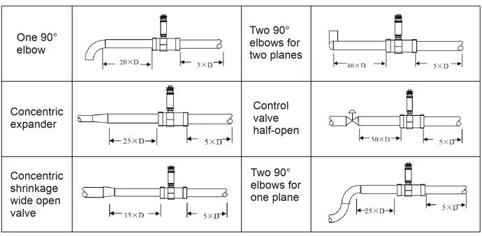
Installation
