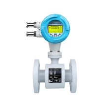
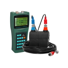
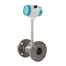
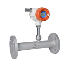
Introductions
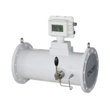
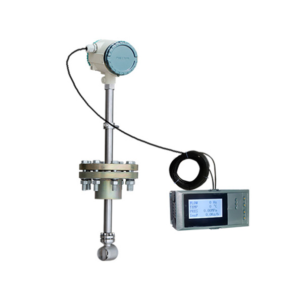
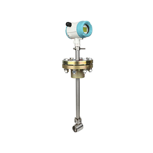
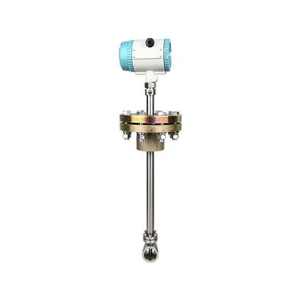
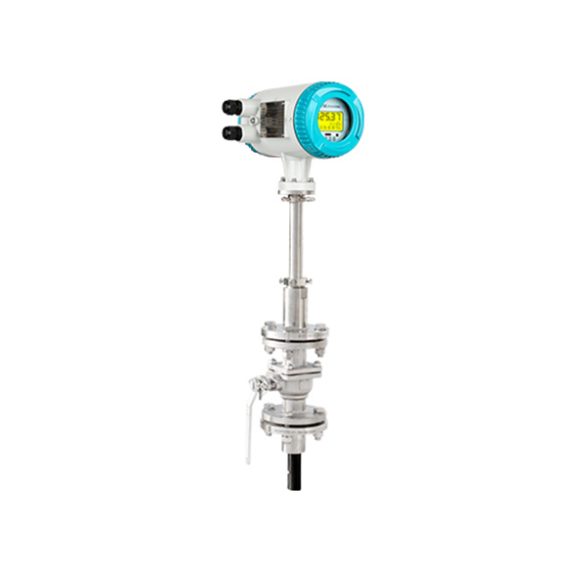
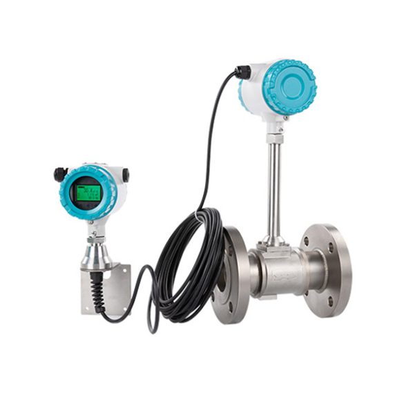
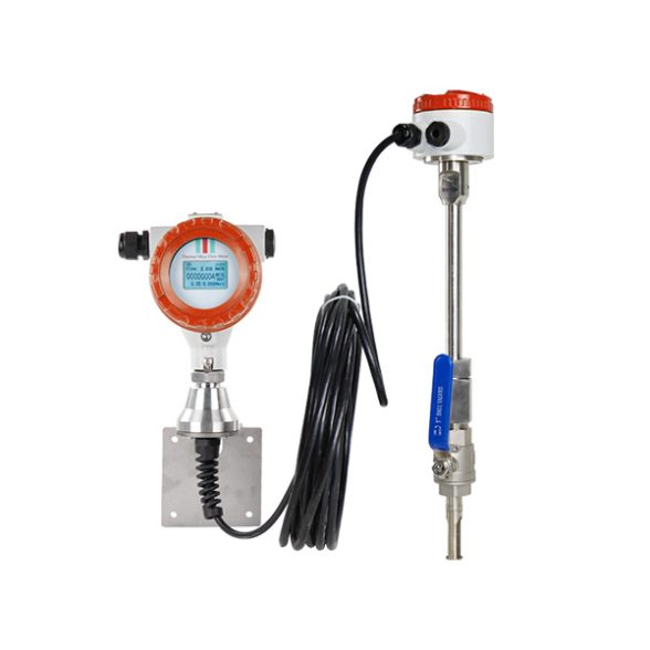
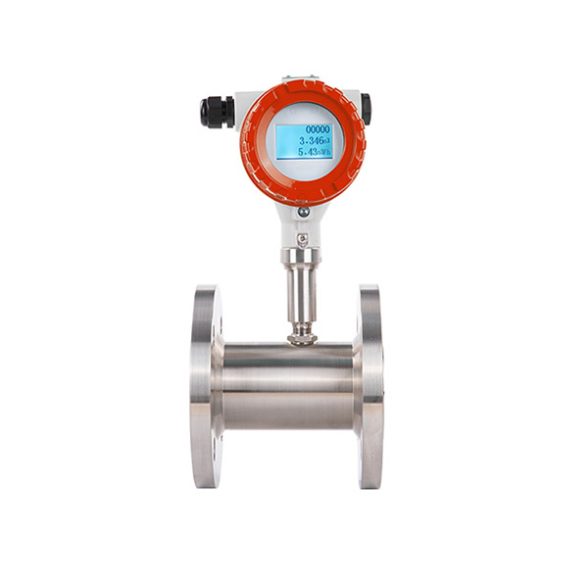
WESDUN is a manufacturer specializing in the production of Insertion vortex flow meter;DN80 flow meter;Steam flow meter.Insertion vortex flow meter works based on Carmen and Strouhal relevant spiral produce and on the theory of the flow relationship.
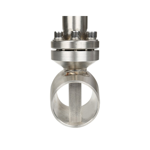
As shown in picture, In the meter body vertical insert a triangular prism root namely the happening of the body, when eddies of medium flow through the table body, in triangular prism behind the alternate produce in opposite directions regular karman swirl.
Its spiral separation and the flow of the medium frequency F speed by sensing head is proportional to the V detected the number of spiral,can measure the flow velocity,again according tp the table body mouth.
Main technical Parameters
| Technical Performance Parameters | |
| Measured Medium | Liquid, Gas, Steam |
| Medium Temp | -40℃~+200℃;-40℃~+280℃;40℃~+350C |
| Nominal Pressure | 1.6MPa;2.5MPa;4.0MPa;6.4MPa (Other pressure can be custom,need consult supplier) |
| Accuracy | 1.0%(Flange),1.5%(Insertion) |
| Measuring range ratio | 1:10(Standard air condition as reference)1:15(Liquid) |
| Flow Range | Liquid:0.4-7.0m/s;Gas:4.0-60.0m/s;Steam:5.0-70.0m/s |
| Specifications | DN15-DN300(FIange),DN80-DN2000(Insertion),DN15-DN100(Thread),DN15-DN300(Wafer),DN15-DN100(Sanitary) |
| Material | SS304(Standard),SS316(Optional) |
| Pressure Loss Coefficient | Cd≤2.6 |
| Vibration Acceleration Allowed | ≤0.2g |
| IEP ATEX | II 1G Ex ia IIC T5 Ga |
| Ambient Condition | Ambient Temp:-40°C-65°C(Non-explosion-proof site);-20°C-55°C(Explosion-proof site)Relative Humidity:≤85%Pressure:86kPa-106kPa |
| Power Supply | 12-24V/DC or 3.6V battery powered |
| Signal Output | Pulse frequency signal2-3000Hz, Low level≤1V, high level≥6V |
| Two-wire system 4-20 signal(isolated output),Load≤500 | |
| Flow Range | ||||
| Size(mm) | Liquid(Reference medium: normal temperature water ,m3 /h) | Gas(Reference medium:20℃,101325pa condition air, m3/ h) | ||
| Standard | Extended | Standard | Extended | |
| 15 | 0.8~6 | 0.5~8 | 6~40 | 5~50 |
| 20 | 1~8 | 0.5~12 | 8~50 | 6~60 |
| 25 | 1.5~12 | 0.8~16 | 10~80 | 8~120 |
| 40 | 2.5~30 | 2~40 | 25~200 | 20~300 |
| 50 | 3~50 | 2.5~60 | 30~300 | 25~500 |
| 65 | 5~80 | 4~100 | 50~500 | 40~800 |
| 80 | 8~120 | 6~160 | 80~800 | 60~1200 |
| 100 | 12~200 | 8~250 | 120~1200 | 100~2000 |
| 125 | 20~300 | 12~400 | 160~1600 | 150~3000 |
| 150 | 30~400 | 18~600 | 250~2500 | 200~4000 |
| 200 | 50~800 | 30~1200 | 400~4000 | 350~8000 |
| 250 | 80~1200 | 40~1600 | 600~6000 | 500~12000 |
| 300 | 100~1600 | 60~2500 | 1000~10000 | 600~16000 |
| 400 | 200~3000 | 120~5000 | 1600~16000 | 1000~25000 |
| 500 | 300~5000 | 200~8000 | 2500~25000 | 1600~40000 |
| 600 | 500~8000 | 300~10000 | 4000~40000 | 2500~60000 |
| Super heated Steam Density Value (relative pressure & temperature) Unit: Kg/m3 | ||||||
| Absolute Pressure (Mpa) | Temperature(°C) | |||||
| 150 | 200 | 250 | 300 | 350 | 400 | |
| 0.1 | 0.52 | 0.46 | 0.42 | 0.38 | ||
| 0.15 | 0.78 | 0.7 | 0.62 | 0.57 | 0.52 | 0.49 |
| 0.2 | 1.04 | 0.93 | 0.83 | 0.76 | 0.69 | 0.65 |
| 0.25 | 1.31 | 1.16 | 1.04 | 0.95 | 0.87 | 0.81 |
| 0.33 | 1.58 | 1.39 | 1.25 | 1.14 | 1.05 | 0.97 |
| 0.35 | 1.85 | 1.63 | 1.46 | 1.33 | 1.22 | 1.13 |
| 0.4 | 2.12 | 1.87 | 1.68 | 1.52 | 1.4 | 1.29 |
| 0.5 | 2.35 | 2.11 | 1.91 | 1.75 | 1.62 | |
| 0.6 | 2.84 | 2.54 | 2.3 | 2.11 | 1.95 | |
| 0.7 | 3.33 | 2.97 | 2.69 | 2.46 | 2.27 | |
| 0.8 | 3.83 | 3.41 | 3.08 | 2.82 | 2.6 | |
| 1 | 4.86 | 4.3 | 3.88 | 3.54 | 3.26 | |
| 1.2 | 5.91 | 5.2 | 4.67 | 4.26 | 3.92 | |
| 1.5 | 7.55 | 6.58 | 5.89 | 5.36 | 4.93 | |
| 2 | 8.968 | 7.97 | 7.21 | 6.62 | ||
| 2.5 | 11.5 | 10.1 | 9.11 | 8.33 | ||
| 3 | 14.2 | 12.3 | 11.1 | 10.1 | ||
| 3.5 | 17 | 14.6 | 13 | 11.8 | ||
| 4 | 17 | 15.1 | 13.6 | |||
Features
- Flange&body: integrally forged pieces, it will avoid break down into pieces. 100% SS304 material,we can provide material report.
- Circuit Board: Digital circuit board,anti most of the supplier use analog circuit board,digital circuit board enjoy the advantages of anti-vibration and anti-interference.
- Flow converter: Distinctive modular design, amateurs can operate, disassemble and assemble easily, it will avoid accident risks.
- Welding: adopt the advanced fish scale technology,which makes the welding seam looks nice and smooth.
- Japan OVAL technology with embedded-type sensor, triangular prism will not fall off, we already apply for patent.
- Our medium temperature sensor can measure highest temperature around 350℃,normal it is -40~250℃
Selection
| Table 1: Special Mark | ||||||||
| Format | Common | Standard Signal Output | Intrinsically Safe Explosion-proof | On Site Display | High Temperature(350℃) | Temperature Compensation | Pressure Compensation | Temperature&Pressure Compensation |
| Mark No. | None | M | B | X | G | W | Y | Z |
| Table 2: Nominal Diameter Flange /Wafer Type | ||||||||||||||
| Size | 15 | 20 | 25 | 32 | 40 | 50 | 65 | 80 | 100 | 125 | 150 | 200 | 250 | 300 |
| Mark No . | 150 | 200 | 250 | 320 | 400 | 500 | 650 | 800 | 101 | 125 | 151 | 201 | 251 | 301 |
| Insertion type | |||||||||||||||||||
| Size | 100 | 125 | 150 | 200 | 250 | 300 | 350 | 400 | 500 | 600 | 700 | 800 | 900 | 1000 | 1200 | 1400 | 1600 | 1800 | 2000 |
| Mark No. | 100 | 125 | 151 | 201 | 251 | 301 | 351 | 401 | 501 | 601 | 701 | 801 | 901 | 102 | 122 | 142 | 162 | 182 | 202 |
| Table 3:Measured Medium | |||||
| Measured Medium | Liquid | Common Gas | Saturated Steam | Superheated Steam | Others |
| Mark No. | 1 | 2 | 3 | 4 | 5 |
| Table 4:Connection Mode | ||||
| Connection Mode | Flange Connection | Wafer Connection | Insertion Type | Others |
| Mark No. | 1 | 2 | 3 | 4 |
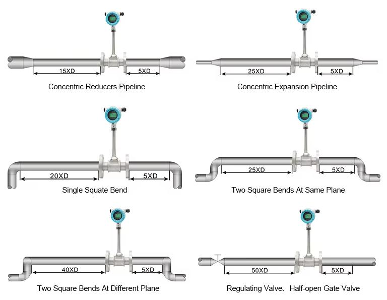
Installation
