Introductions
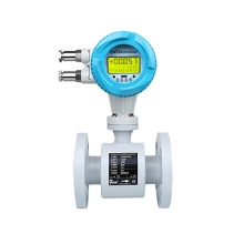
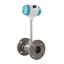
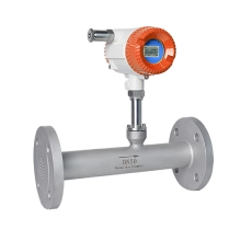
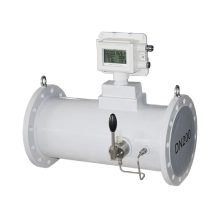
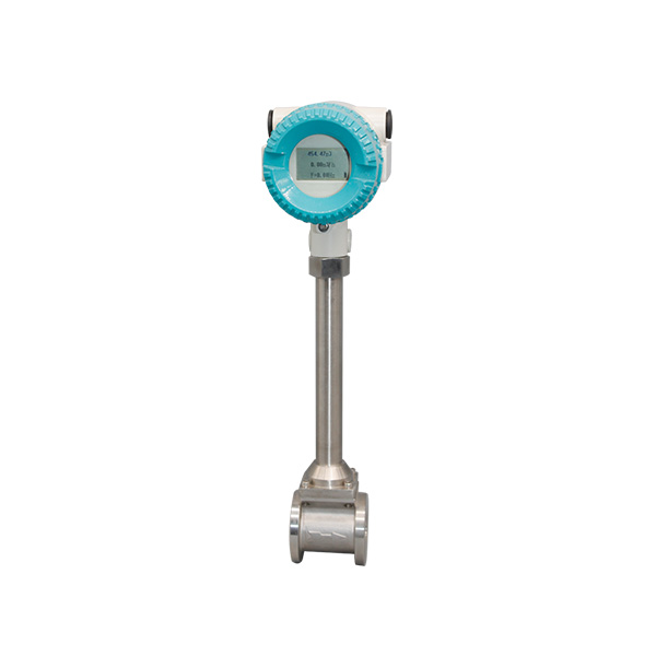
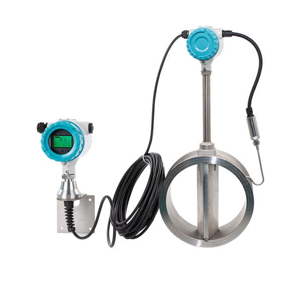
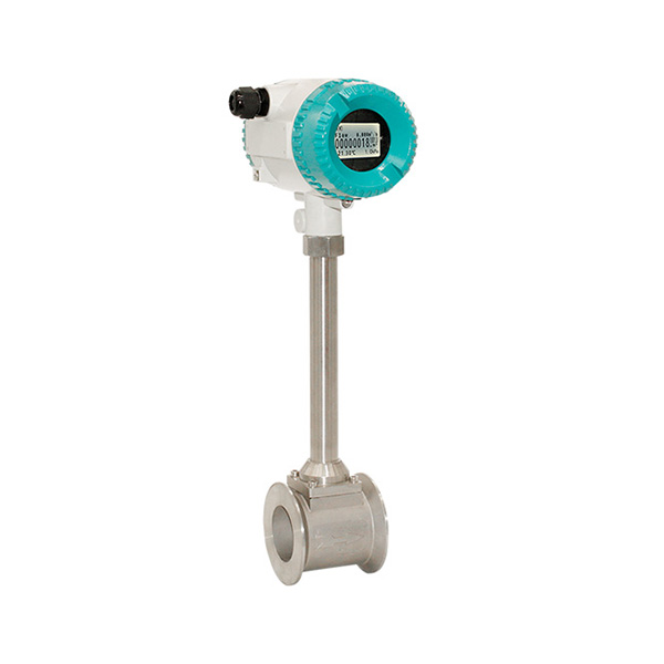
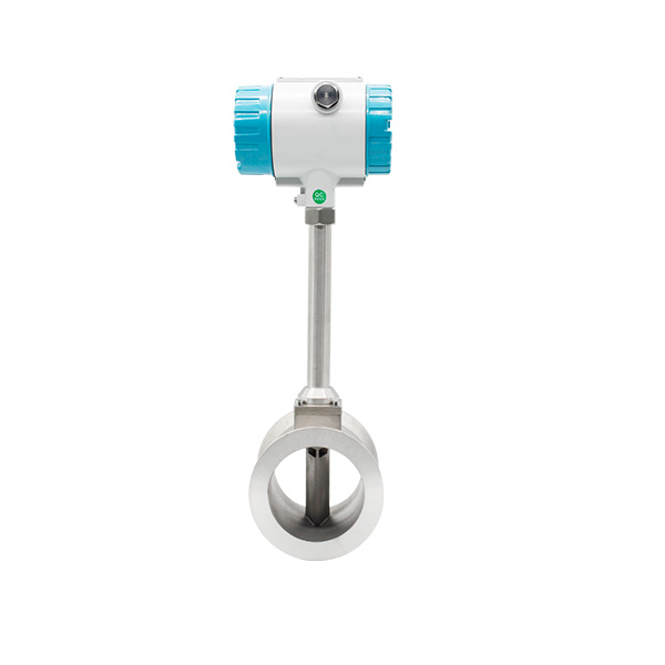
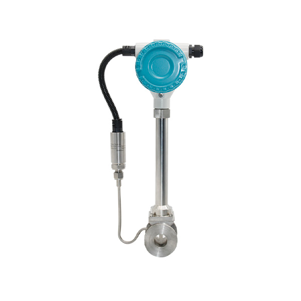
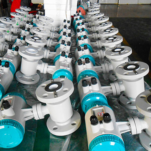
WESDUN is a manufacturer specializing in the production of Wafer vortex flow meter;DN15 flow meter;Steam flow meter.Wafer Connection Vortex Flow Meter: Engineered for precision in tight spaces.
Its slim, clamp-style design fits seamlessly between flanges—no major pipe modifications needed, cutting installation time by 50%.
Delivers ±1% accuracy across liquids, gases, and steam, with a wide range (0.05-1000 m³/h) to handle diverse industrial flows.
304/316L stainless steel construction resists corrosion, while the robust sensor ignores vibrations, ensuring stable readings in harsh environments.
Low pressure drop boosts energy efficiency. Equipped with 4-20mA/RS485 outputs for easy integration with control systems.
Main technical Parameters
| Technical Performance Parameters | |
| Measured Medium | Liquid, Gas, Steam |
| Medium Temp | -40℃~+200℃;-40℃~+280℃;40℃~+350C |
| Nominal Pressure | 1.6MPa;2.5MPa;4.0MPa;6.4MPa (Other pressure can be custom,need consult supplier) |
| Accuracy | 1.0%(Flange),1.5%(Insertion) |
| Measuring range ratio | 1:10(Standard air condition as reference)1:15(Liquid) |
| Flow Range | Liquid:0.4-7.0m/s;Gas:4.0-60.0m/s;Steam:5.0-70.0m/s |
| Specifications | DN15-DN300(FIange),DN80-DN2000(Insertion),DN15-DN100(Thread),DN15-DN300(Wafer),DN15-DN100(Sanitary) |
| Material | SS304(Standard),SS316(Optional) |
| Pressure Loss Coefficient | Cd≤2.6 |
| Vibration Acceleration Allowed | ≤0.2g |
| IEP ATEX | II 1G Ex ia IIC T5 Ga |
| Ambient Condition | Ambient Temp:-40°C-65°C(Non-explosion-proof site);-20°C-55°C(Explosion-proof site)Relative Humidity:≤85%Pressure:86kPa-106kPa |
| Power Supply | 12-24V/DC or 3.6V battery powered |
| Signal Output | Pulse frequency signal2-3000Hz, Low level≤1V, high level≥6V |
| Two-wire system 4-20 signal(isolated output),Load≤500 | |
| Flow Range | ||||
| Size(mm) | Liquid(Reference medium: normal temperature water ,m3 /h) | Gas(Reference medium:20℃,101325pa conditionair, m3/ h) | ||
| Standard | Extended | Standard | Extended | |
| 15 | 0.8~6 | 0.5~8 | 6~40 | 5~50 |
| 20 | 1~8 | 0.5~12 | 8~50 | 6~60 |
| 25 | 1.5~12 | 0.8~16 | 10~80 | 8~120 |
| 40 | 2.5~30 | 2~40 | 25~200 | 20~300 |
| 50 | 3~50 | 2.5~60 | 30~300 | 25~500 |
| 65 | 5~80 | 4~100 | 50~500 | 40~800 |
| 80 | 8~120 | 6~160 | 80~800 | 60~1200 |
| 100 | 12~200 | 8~250 | 120~1200 | 100~2000 |
| 125 | 20~300 | 12~400 | 160~1600 | 150~3000 |
| 150 | 30~400 | 18~600 | 250~2500 | 200~4000 |
| 200 | 50~800 | 30~1200 | 400~4000 | 350~8000 |
| 250 | 80~1200 | 40~1600 | 600~6000 | 500~12000 |
| 300 | 100~1600 | 60~2500 | 1000~10000 | 600~16000 |
| 400 | 200~3000 | 120~5000 | 1600~16000 | 1000~25000 |
| 500 | 300~5000 | 200~8000 | 2500~25000 | 1600~40000 |
| 600 | 500~8000 | 300~10000 | 4000~40000 | 2500~60000 |
| Flow Range | ||||
| Size(mm) | Liquid(Reference medium: normal temperature water ,m3 /h) | Gas(Reference medium:20℃,101325pa condition air, m3/ h) | ||
| Standard | Extended | Standard | Extended | |
| 15 | 0.8~6 | 0.5~8 | 6~40 | 5~50 |
| 20 | 1~8 | 0.5~12 | 8~50 | 6~60 |
| 25 | 1.5~12 | 0.8~16 | 10~80 | 8~120 |
| 40 | 2.5~30 | 2~40 | 25~200 | 20~300 |
| 50 | 3~50 | 2.5~60 | 30~300 | 25~500 |
| 65 | 5~80 | 4~100 | 50~500 | 40~800 |
| 80 | 8~120 | 6~160 | 80~800 | 60~1200 |
| 100 | 12~200 | 8~250 | 120~1200 | 100~2000 |
| 125 | 20~300 | 12~400 | 160~1600 | 150~3000 |
| 150 | 30~400 | 18~600 | 250~2500 | 200~4000 |
| 200 | 50~800 | 30~1200 | 400~4000 | 350~8000 |
| 250 | 80~1200 | 40~1600 | 600~6000 | 500~12000 |
| 300 | 100~1600 | 60~2500 | 1000~10000 | 600~16000 |
| 400 | 200~3000 | 120~5000 | 1600~16000 | 1000~25000 |
| 500 | 300~5000 | 200~8000 | 2500~25000 | 1600~40000 |
| 600 | 500~8000 | 300~10000 | 4000~40000 | 2500~60000 |
| Super heated Steam Density Value (relative pressure & temperature) Unit: Kg/m3 | ||||||
| Absolute Pressure (Mpa) | Temperature(°C) | |||||
| 150 | 200 | 250 | 300 | 350 | 400 | |
| 0.1 | 0.52 | 0.46 | 0.42 | 0.38 | ||
| 0.15 | 0.78 | 0.7 | 0.62 | 0.57 | 0.52 | 0.49 |
| 0.2 | 1.04 | 0.93 | 0.83 | 0.76 | 0.69 | 0.65 |
| 0.25 | 1.31 | 1.16 | 1.04 | 0.95 | 0.87 | 0.81 |
| 0.33 | 1.58 | 1.39 | 1.25 | 1.14 | 1.05 | 0.97 |
| 0.35 | 1.85 | 1.63 | 1.46 | 1.33 | 1.22 | 1.13 |
| 0.4 | 2.12 | 1.87 | 1.68 | 1.52 | 1.4 | 1.29 |
| 0.5 | 2.35 | 2.11 | 1.91 | 1.75 | 1.62 | |
| 0.6 | 2.84 | 2.54 | 2.3 | 2.11 | 1.95 | |
| 0.7 | 3.33 | 2.97 | 2.69 | 2.46 | 2.27 | |
| 0.8 | 3.83 | 3.41 | 3.08 | 2.82 | 2.6 | |
| 1 | 4.86 | 4.3 | 3.88 | 3.54 | 3.26 | |
| 1.2 | 5.91 | 5.2 | 4.67 | 4.26 | 3.92 | |
| 1.5 | 7.55 | 6.58 | 5.89 | 5.36 | 4.93 | |
| 2 | 8.968 | 7.97 | 7.21 | 6.62 | ||
| 2.5 | 11.5 | 10.1 | 9.11 | 8.33 | ||
| 3 | 14.2 | 12.3 | 11.1 | 10.1 | ||
| 3.5 | 17 | 14.6 | 13 | 11.8 | ||
| 4 | 17 | 15.1 | 13.6 | |||
Features
- Flange&body: integrally forged pieces, it will avoid break down into pieces. 100% SS304 material,we can provide material report.
- Circuit Board: Digital circuit board,anti most of the supplier use analog circuit board,digital circuit board enjoy the advantages of anti-vibration and anti-interference.
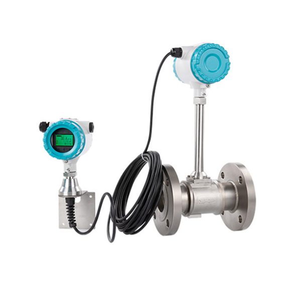
- Flow converter: Distinctive modular design, amateurs can operate, disassemble and assemble easily, it will avoid accident risks.
- Welding: adopt the advanced fish scale technology,which makes the welding seam looks nice and smooth.
- Japan OVAL technology with embedded-type sensor, triangular prism will not fall off, we already apply for patent.
- Our medium temperature sensor can measure highest temperature around 350℃,normal it is -40~250℃
Selection
| Table 1: Special Mark | ||||||||
| Format | Common | Standard Signal Output | Intrinsically Safe Explosion-proof | On Site Display | High Temperature(350℃) | Temperature Compensation | Pressure Compensation | Temperature&Pressure Compensation |
| Mark No. | None | M | B | X | G | W | Y | Z |
| Table 2: Nominal Diameter Flange /Wafer Type | ||||||||||||||
| Size | 15 | 20 | 25 | 32 | 40 | 50 | 65 | 80 | 100 | 125 | 150 | 200 | 250 | 300 |
| Mark No . | 150 | 200 | 250 | 320 | 400 | 500 | 650 | 800 | 101 | 125 | 151 | 201 | 251 | 301 |
| Insertion type | |||||||||||||||||||
| Size | 100 | 125 | 150 | 200 | 250 | 300 | 350 | 400 | 500 | 600 | 700 | 800 | 900 | 1000 | 1200 | 1400 | 1600 | 1800 | 2000 |
| Mark No. | 100 | 125 | 151 | 201 | 251 | 301 | 351 | 401 | 501 | 601 | 701 | 801 | 901 | 102 | 122 | 142 | 162 | 182 | 202 |
| Table 3:Measured Medium | |||||
| Measured Medium | Liquid | Common Gas | Saturated Steam | Superheated Steam | Others |
| MarkNo. | 1 | 2 | 3 | 4 | 5 |
| Table 4:Connection Mode | ||||
| Connection Mode | Flange Connection | Wafer Connection | Insertion Type | Others |
| Mark No. | 1 | 2 | 3 | 4 |
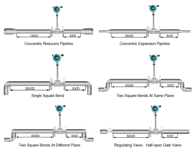
Installation
