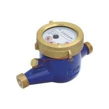
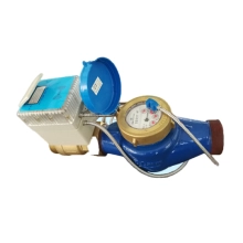
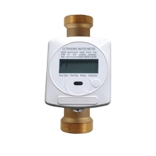
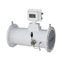
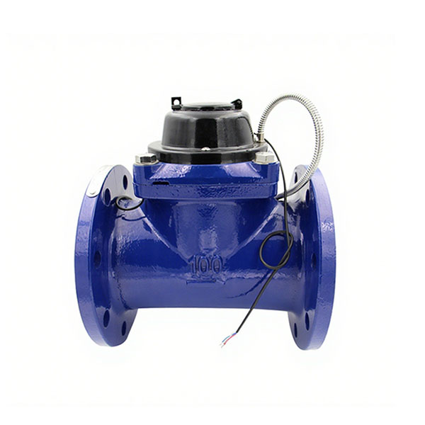
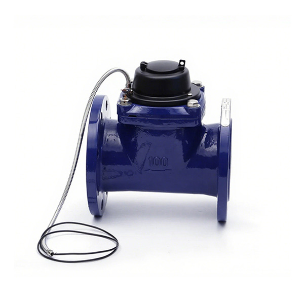
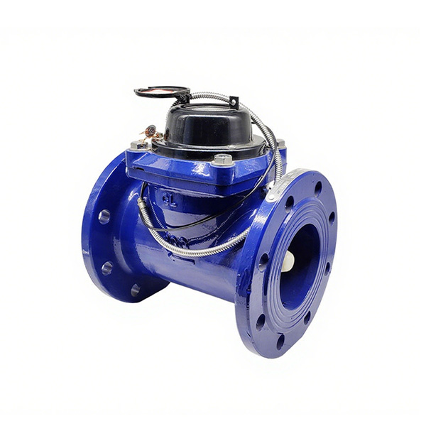
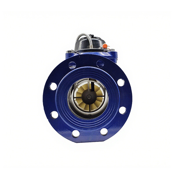
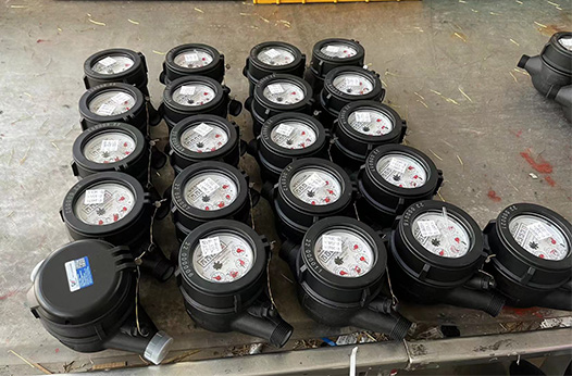
This type water meter is a flow meter used to measure the total volume of water flowing through the tap water pipe, and can be equipped with remote transmission.WESDUN LXLC(R)-350-600mm Removable element woltman cold(hot) water meter is Dry-dial water meter;LXLC water meter;Magnetic drive water meter.
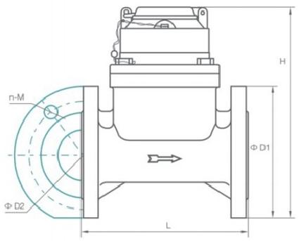
Main Technical Parameters
Type
Size
L
H
Connecting Flange
ΦD1Outside Diameter
φD2 BoltCircleDiameter
ConnectingBolts{n-M)
WorkingPressure(MPa)
mm
LXLC-350
350
500
590
505
460
16-M20
1.0
520
470
16-M24
1.6
555
490
16-M30
2.5
LXLC-400
400
600
660
565
515
16-M24
1.0
580
525
16-M27
1.6
620
550
16-M33
2.5
LXLC-450
450
600
700
615
565
20-M24
1.0
640
585
20-M27
1.6
670
600
20-M33
2.5
LXLC-500
500
800
760
670
620
20-M24
1.0
715
650
20-M30
1.6
730
660
20-M33
2.5
LXLC-600
600
500 Or 800
880
780
725
20-M27
1.0
840
770
20-M33
1.6
845
770
20-M36
2.5
Type
Sizemm
class
QsOverload flow
QPPermanent flow
QtTransitionalflow
Qminreading
Min. Reading
Max.Reading
m³/h
m³
LXLC-350
350
A
1600
800
240
64
0.02
999,999,999
B
160
24
LXLC-400
400
A
2000
1000
300
80
0.02
999,999,999
B
200
30
LXLC-450
450
A
2000
1000
300
80
0.02
999,999,999
B
200
30
XLC-500
500
A
3000
1500
450
120
0.029
999,999,999
B
300
45
LXLC-600
600
A
6000
3000
900
240
0.02
999,999,999
B
600
90
Features
Dry-dial, Magnetic drive.
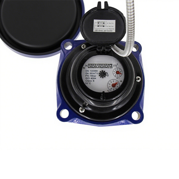
Vacuum sealed register ensures the dial keep free from fog and Keep the reading clear in a long term service.
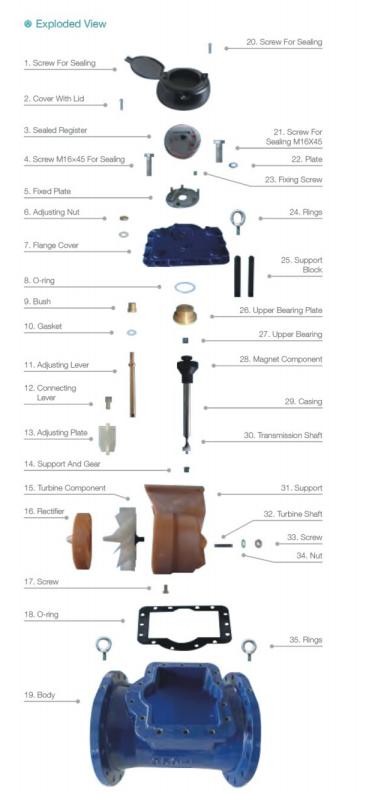
Removable element unit and strong universality, easy installation and maintenance.
Measuring high flow rate with low head loss.
Remote transmission device can be added upon request:such as Reed Switch or Hall, Pulse Output:100000L/P10000L/P.
Technical data conform to ISO 4064 standard.
Selection/ installation and Use
Select the water meter type, metering characteristics and caliber based on the working conditions of the water supply facility. Its expected flow rate should be compatible with the Q1 to Q3 flow rates of the water meter.
Avoid excessive stress on the water meter caused by pipes and fittings. If necessary, mount the water meter on a base or bracket. Secure the upstream and downstream pipes properly to prevent any displacement from its own weight when removing the water meter or disconnecting either side.
Install the water meter horizontally. Align the arrow on the meter body with the direction of water flow in the pipeline. Install control valves both upstream and downstream of the water meter. Keep the inlet and outlet valves fully open during use. Also, fit an expansion joint or soft neck joint downstream of the water meter for easier meter removal and maintenance.
To ensure long and accurate operation of the water meter, always keep the meter and pipeline full of water. If air may enter the water meter, install a vent valve upstream
Choose a protected installation site for the water meter, away from direct sunlight, freezing, pollution and flooding. In high‑cold areas, avoid installing water meters outdoors.If you must install them outdoors, take sun protection and anti‑freezing measures to prevent sun damage or freezing cracks that would affect normal operation. Avoid sudden changes in the flow cross-section near the water meter.
Measures should be taken to prevent adverse hydraulic conditions (cavitation, surge, water hammer) to prevent water meter damage.
Before installing the water meter, remove all sand, gravel, hemp and other debris from the pipe. When installing the water meter, check its connection length carefully. If the distance between the two pipe ends exceeds the water meter’s connection length, adjust the pipe distance to match it. Otherwise, forcing installation with an excessive distance will break and damage the water meter connection flange. If the distance is too small, you cannot install the water meter. If the two ends of the water meter are not aligned on the same axis, use other methods to align the pipes and meet the water meter installation requirements.
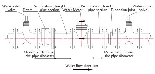
When installing a water meter, it should be installed on a straight pipeline. Do not install the water meter at a height position that changes suddenly. Generally, install a straight pipe section of the same diameter (D) as the water meter upstream and downstream, with lengths of 10D and 5D respectively. Make the upstream straight pipe section as long as possible, and place it between the control valve and the water meter. If you cannot meet this requirement, install a straightening device upstream. Check the level when installing the water meter to avoid inclined operation, which may cause inaccurate measurement. Also, avoid sudden changes in the flow section near the water meter.
During long-term use, install a filter with the same nominal diameter as the water meter behind the control valve. This prevents sand, gravel and other debris from entering the water meter, affecting accurate measurement or causing damage. Remove and clean the filter regularly, and clear out accumulated impurities to ensure the water meter measures accurately.
If the above adverse conditions occur, you should contact the local water supply department or the management department of the water meter and solve them. Do not disassemble or assemble it by yourself.
If the water meter pointer moves slightly when not in use, it is usually due to air in the pipeline or unstable water pressure. Close the upstream control valve or install a check valve at the water inlet of the meter when the water meter is not in use.