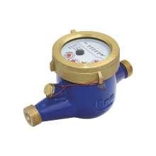
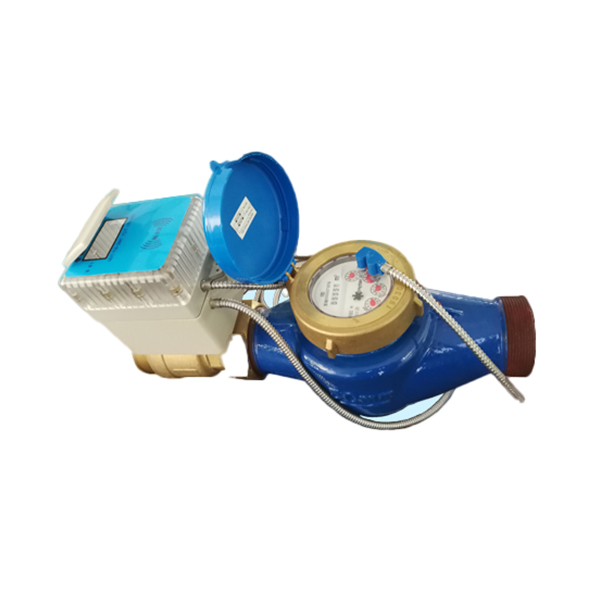
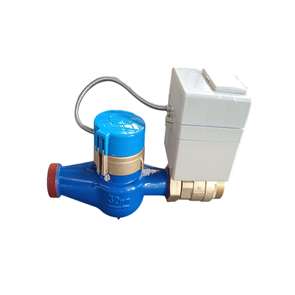
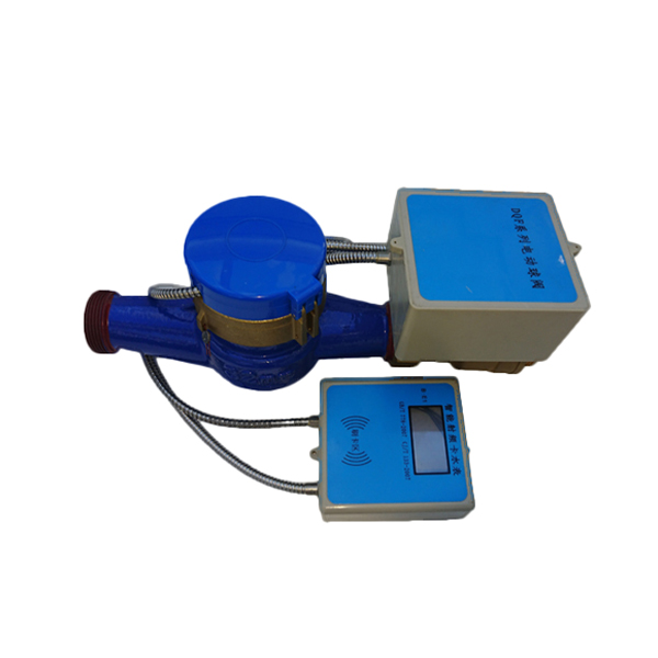
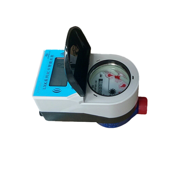
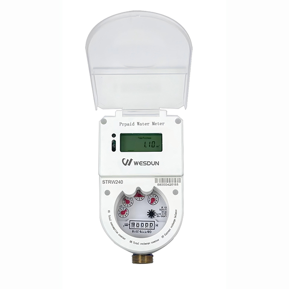
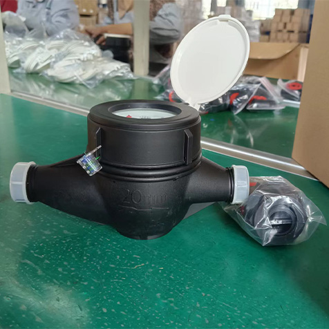
This series of water meters are used to measure the total volume of cold (hot) water flowing through the tap water pipe and realize prepayment functions: valve closing for arrears, tiered water price, etc.WESDUN is a manufacturer specializing in the production of Prepayment water meter;DN15 water meter;Cold hot water meter.
Main Technical Parameters
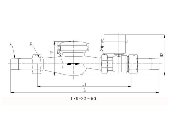
Diameter
L
L1
W
H1
H2 Connection thread
Connection thread
mm
d
D
15
258
165
90
120
200
R1/2
G3/4B
20
299
195
90
120
200
R3/4
G1B
25
345
225
90
120
200
R1
G1-1/4B
32
452
328
99
206
253
R1-1/4
G1-1/2B
40
485
355
119
222
269
R1-1/2
G2B
50
575
406
143
255
302
R2
G2-1/2B
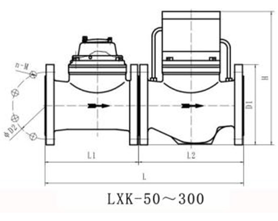
Diameter
Water meter L1
Valve L2
Total L
H
Outer diameter D1
Center distanceD2
Connecting bolts
mm
n-M
50
200
220
420
335
165
125
4-M16
65
200
220
420
345
185
145
4-M16
80
225
300
525
375
200
160
8-M16
100
250
340
590
415
220
180
8-M16
125
250
350
600
460
250
210
8-M16
150
300
400
700
525
285
240
8-M20
200
350
440
790
560
340
295
8-M20(1.0Mpa)
12-M20(1.6Mpa)
250
450
550
1000
660
395
350
12-M20(1.0Mpa)
405
355
12-M24(1.6Mpa)
300
500
640
1140
800
445
400
12-M20(1.0Mpa)
460
410
12-M24(1.6Mpa)
Nominal diametermm
Metering characteristics
Q4 Overload flow
Q3 Nominal flow
Q2Demarcation flow
Q1Mini flow
Minireading
Maxreading
m3/h
m3
15
R100
3.125
2.5
0.04
0.025
0.00005
99.999
20
5
4
0.064
0.04
0.00005
99.999
25
7.875
6.3
0.1
0.063
0.00005
99.999
32
12.5
10
0.16
0.1
0.00005
99.999
40
20
16
0.256
0.16
0.00005
99.999
50
31.25
25
0.4
0.25
0.00005
99.999
50
R50
31.25
25
0.8
0.5
0.0005
999.999
65
50
40
1.28
0.8
0.0005
999.999
80
78.75
63
2
1.26
0.002
999.999
100
125
100
3.2
2
0.002
999.999
125
200
160
5.12
3.2
0.002
999.999
150
312.5
250
8
5
0.002
999.999
200
500
400
12.8
8
0.002
999.999
250
787.5
630
20.16
12.6
0.02
9999.999
300
1250
1000
32
20.16
0.02
9999.999
Features
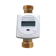
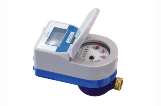
DN15-25 adopts integrated meter and valve structure, with the same size as ordinary water meters, which is easy to replace and upgrade;
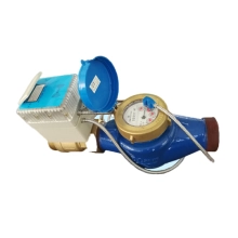
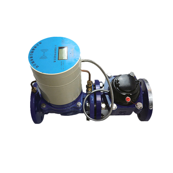
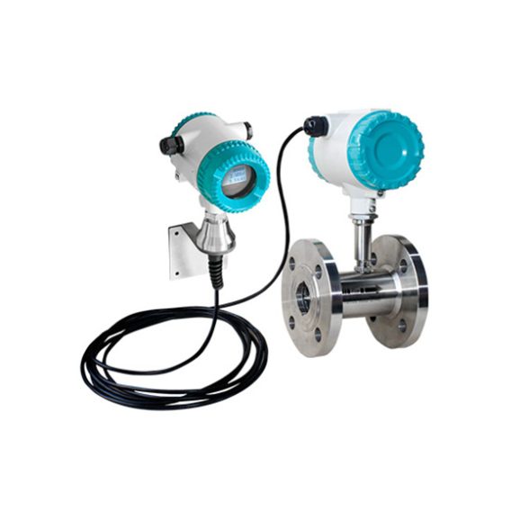
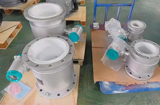
DN32-50 adopts independent meter and valve structure, modular production, and easy maintenance;
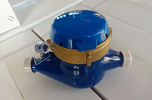
DN15-50 and above all use rotary vane water meter as the measuring carrier, ball valve suspension structure, small switching torque, long service life, anti-blocking, no leakage;
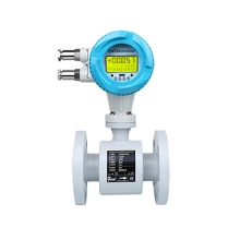
DN50-300 uses LXLC series water meter as the measuring carrier, pilot valve control, advanced structure, always clear reading, small pressure loss, easy installation and maintenance;
One card one meter, encryption protection; automatic valve closing protection under strong magnetic interference;
Multiple user types are optional, three-step water volume and unit price can be set to be compatible with single rate billing.
Selection, installation and Use
Match the expected flow rate to the water meter’s Q1–Q3 flow range.Do not select a water meter based solely on the pipe diameter without considering the common flow rate.
Protect the water meter from excessive stress caused by pipes and fittings, and keep all components from shifting under their own weight.
Install the water meter horizontally, and align the arrow on the meter body with the direction of water flow in the pipe. Fit control valves both upstream and downstream of the water meter, and keep the inlet and outlet valves fully open during use. Also, install expansion joints or flexible joints downstream of the water meter to make its removal and maintenance more convenient.
To ensure the water meter operates reliably and measures accurately over a long period, always keep the meter and the pipeline full of water.
If air may enter the water meter, install a vent valve upstream of it.
Install the water meter in a location protected from sunlight, freezing, pollution and flooding. In high-cold regions, avoid installing water meters outdoors. If outdoor installation is necessary, take sun protection and anti-freeze measures to keep the meter from sun damage or freezing cracks that affect normal use. Avoid sudden changes in the flow cross-section near the water meter.
Take measures to protect the water meter from damage caused by adverse hydraulic conditions such as cavitation, surge and water hammer.
Before installing the water meter, remove all sand, gravel, hemp and other debris from the pipeline. Pay attention to the connection length of the water meter during installation. If the distance between the two pipe ends exceeds the meter’s connection length, adjust the pipe distance to match it. Forcing installation with an excessively large distance will break and damage the water meter’s connecting flange. If the distance is too small, you will not be able to install the meter. If the two ends of the water meter are not on the same axis, use other methods to align the pipes to meet the meter’s installation requirements.
Install the water meter on a straight pipeline and avoid locations with sudden height changes. Generally, install a straight pipe section of the same diameter (D) as the meter, with a length of 10D upstream and 5D downstream. In particular, make the upstream straight pipe section as long as possible and place it between the control valve and the water meter. If this cannot be ensured, install a flow straightening device upstream. Check the level during installation to keep the meter from operating in an inclined state, which may cause inaccurate measurement. Also avoid sudden changes in the flow cross-section near the water meter.
For long-term operation, install a filter of the same nominal diameter as the water meter right after the control valve. This keeps sand, gravel and other debris from entering the meter and avoids inaccurate measurement or damage. Remove and clean the filter regularly, and clear out accumulated impurities to ensure stable and accurate metering.
Close the upstream control valve or install a check valve at the water inlet when the water meter is not in use.
If the water meter or its accessories are damaged due to failure to strictly follow the precautions during installation, all damages shall be borne by the installer.